


Descriptive Geometry for Designers — Concepts
Last Updated on: 5th March 2024, 05:43 pm
Descriptive geometry is a fundamental branch of geometry that plays a crucial role in several fields, including design, architecture, and engineering. Understanding basic concepts such as point, line, and plane is essential if you wish to learn descriptive geometry for designers.
The significance of these core concepts in design cannot be overstated. Points, lines, and planes allow designers to convey depth, shape, and spatial relationships in 2D representations, which is particularly valuable when translating complex three-dimensional ideas into 2D media.
Table of Contents
- Core Concepts in Descriptive Geometry
- Notations
- Point
- Point in Projection System
- Line
- Lines Segment
- Reference Lines
- Special Lines of a Plane
- Horizontal Line
- Line of Point or Vanishing Point
- Frontal Line
- Vertical Line
- Profile Line
- Line Parallel to the Ground Line
- Relative Positions of Lines
- Parallelism
- Intersection
- Perpendicularity
- Plane
- Positions of the Planes
- Frontal Plane
- Horizontal Plane
- Vertical Plane
- Edge or Vanishing Plane
- Profile Plane
- Plane Parallel to the Ground Line
- Other Concepts in Descriptive Geometry
- Graphical Projection Concepts
- Summary
- Some Insights
- Any Thoughts?
Core Concepts in Descriptive Geometry
Notations
In this post, we will consider the notations and conventions described by Rodrigo Díaz Minguez for points, lines, and planes.
The elements in space:
- Points are represented by the first capitalized Latin letters of the alphabet (A, B, C… F).
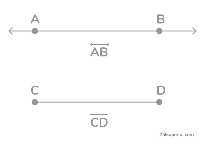
- Lines are represented by the last capital letters (R, S, T… Z) or by the segments that define them with two capital letters (AB, CD…) with A and B being the initial and final points of the segment.
- Planes are represented by lowercase Greek letters or by the middle capital Latin letters of the alphabet (M, N…).
The elements in the plane:
- Points are represented by the first lowercase Latin letters of the alphabet (a, b, c… f).
- The lines are represented by the last lowercase letters (r, s, t… z) or by the segments that define them with two lowercase Latin letters (ab, cd…) with a and b being the initial and final points of the segment.
Let’s get a better understanding of points, lines, and planes, as well as the relationships between them.
Point
In descriptive geometry, a point is the most basic element. It has no dimension, and it is represented as a dot in a 2D drawing or as a coordinate (x, y, z) in a 3D space. Points are essential because they serve as the building blocks for all other geometric elements. They mark specific locations in space and are used to define the vertices of geometric shapes.
Point, as a conceptual element, is not visible except to the mind’s eye. Although it does not really exist, we feel its presence. The hole left by a pin in a sheet of paper or a grain of sand is the closest representation of the point, but keep in mind that it has no:
- width
- length
- depth
Keeping this in mind, a point could be perceived as the intersection of two segments. It is the point in its prolongation that generates the line, which in turn, when extended, will generate a plane whose repetition in space will result in a volume.
It can also be used to represent:
- ends of a line
- the intersection of two lines
- meeting of lines at the edges of a plane or a volume
Point in Projection System
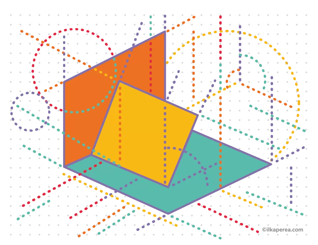
Two projection systems can be used to project a point in space:
- The dihedral system consists of two planes, the horizontal plane of projection and the vertical plane of projection, which are perpendicular to each other.
- The trihedral system is formed by the three planes: the horizontal, vertical, and profile planes of projection, which are perpendicular to the previous two (horizontal and vertical).
In both systems, the x, y, and z coordinates are used to represent the point in space. These coordinates are called:
The “x” coordinate is referred to as the distance.
The “y” coordinate is called the margin or depth.
The “z” coordinate is called height or elevation.
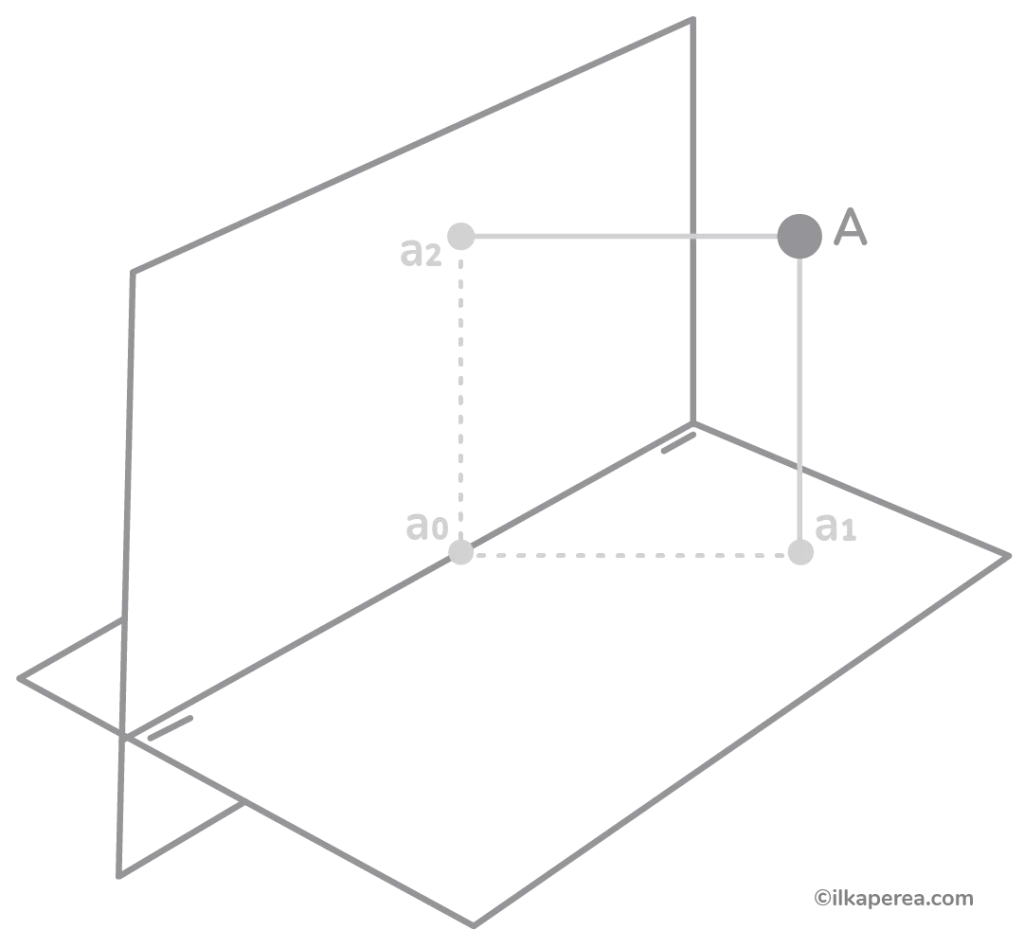
In space, there are infinite points. We will identify them with a capital letter (A or B or C …) and to recognize their position in the different projection planes we will use lowercase letters; for example, for a point “A” in space, we use the following nomenclature:
- a for projection in the Horizontal Plane (H.P.)
- a’ for projection in the Vertical Plane (V.P.)
- a” for projection in the Profile Plane (P.P.)
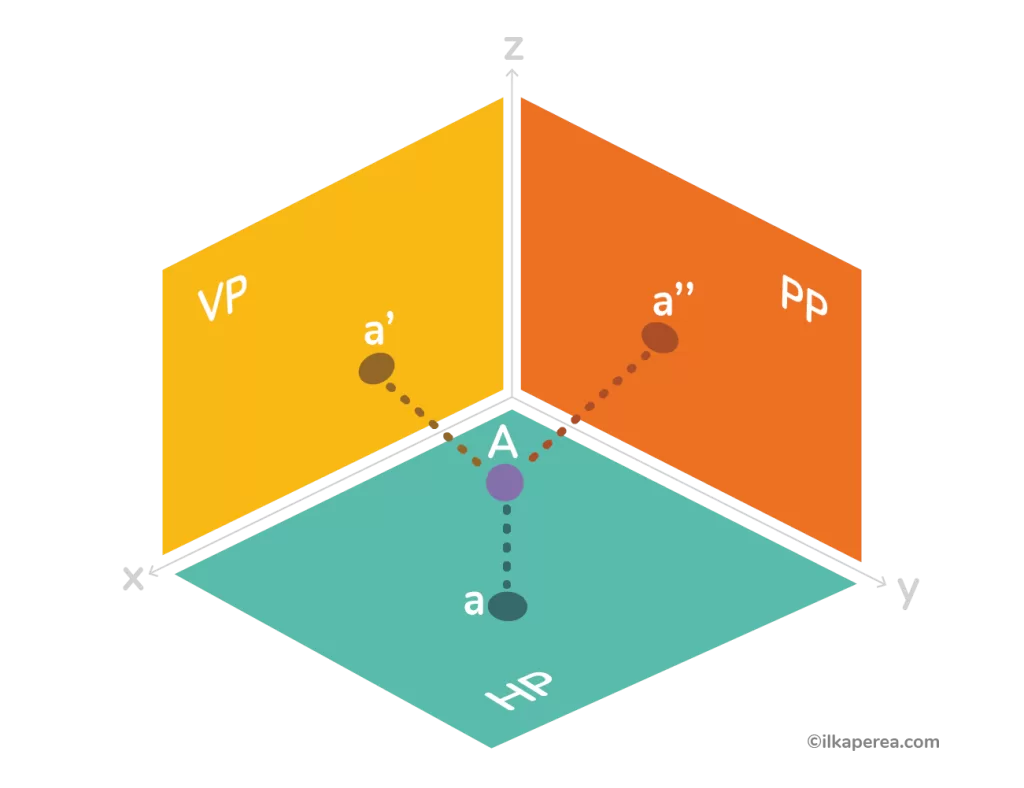
Imagine that planes are walls. You are an object such as a point, a line, or a solid. Your “shadows” were “projected” onto the walls, i.e., the HP, VP, and PP planes.
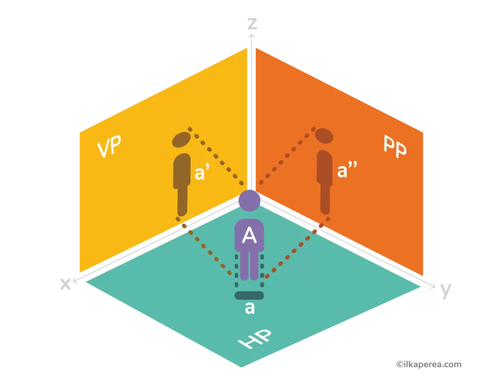
In the dimensioned plane system and dihedral, the projected object reproduces an image of its dimension in true magnitude or at different scales. In axonometric and conic systems, the projection does not show the dimensions of the object in true magnitude.
Line
Lines are defined by a set of points that extend infinitely in both directions. In other words, they are the simplest paths to connect two points. Besides, lines can be straight or curved, and they are crucial for representing edges, outlines, and trajectories in drawings. Descriptive geometry for designers uses various methods to represent lines, such as orthographic projection, where lines in 3D space are projected onto 2D planes.
From a conceptual point of view, the line has
- length (it cannot be measured; it extends infinitely)
but does not:
- width
- depth
In addition, a line has direction and a position in space, which are determined by knowing any two points on it. The line is identified with a lowercase letter, for example, an a, b, or c. However, two capital letters are used to name a segment belonging to it, for example, DE, and read “line DE”.
Lines Segment
In geometry, a line segment describes a distinct part of a straight line that is bounded by two distinct endpoints. It contains every point on the line that is between its endpoints. Thus, a line segment has a definite length and is different from a line, which has no endpoints and extends endlessly in both directions (Figure 4).
In other words, the line segment has
- length (measurable)
but still does not:
- depth
- width
Reference Lines
The lines “Aa1” and “Aa2” determine a plane that intersects with the projection lines at “a2a0” and “a1a0” (Figure 5). Projections at “a2a0” and “a1a0” are perpendicular lines to the ground line.
Special Lines of a Plane
Lines can have a special relationship with the projection planes, either parallel or perpendicular to them. In other words, lines can be aligned with or at a right angle to the projection planes. There are six types of special lines, each of which has a unique relationship with the projection planes. There are horizontal lines, frontal lines, vanishing lines, vertical lines, lines parallel to the ground lines, and profile lines.
Horizontal Line
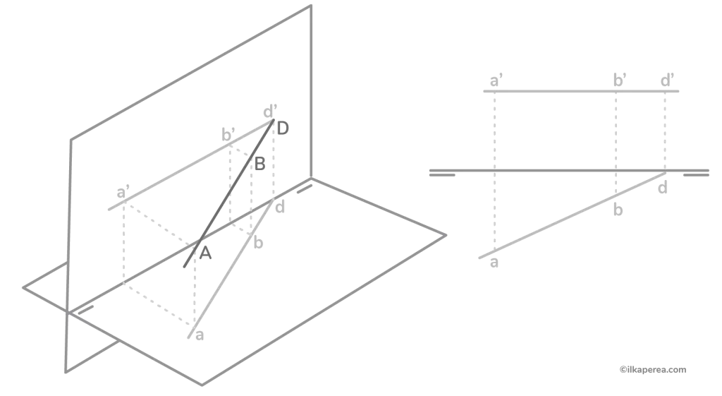
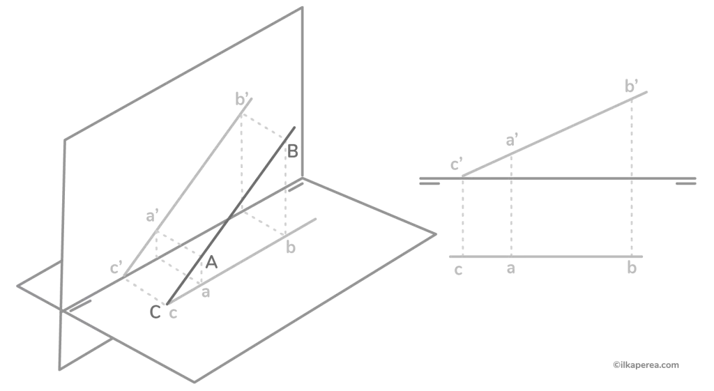
In the dihedral projection, a horizontal line is parallel to the horizontal plane. Conversely, in the beaten plane, it is projected as a line parallel to the ground line in the vertical projection and as an oblique line in the horizontal projection. In Figure 6, point D is the trace (or notable point, where the line crosses the plane) of line AB.
Line of Point or Vanishing Point
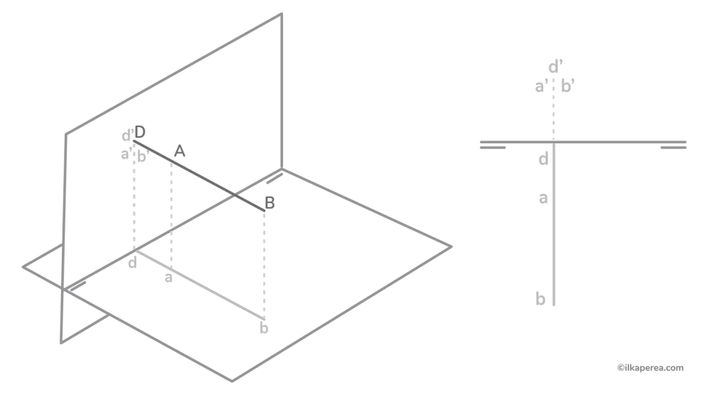
It is a line perpendicular to the vertical plane. It is projected as a point in the vertical projection and as a line perpendicular to the ground line in the horizontal projection. In Figure 7, point D is the trace of the line AB.
Frontal Line
A line parallel to the vertical plane. In the tilted plane, it is projected as an oblique line in the vertical projection and as a line parallel to the ground line in the horizontal projection. In Figure 8, point C is the trace of the line AB.
Vertical Line
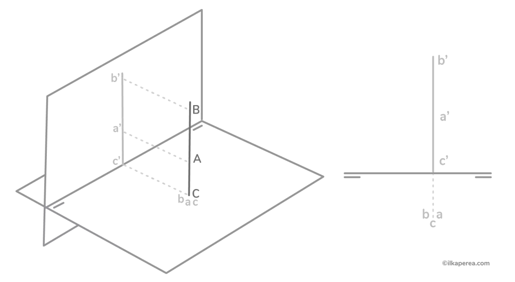
In the dihedral projection, a vertical line is perpendicular to the horizontal plane. Although, in the tilted plane, it is projected as a line perpendicular to the ground line in vertical projection and as a point in horizontal projection. In Figure 9, point C is the trace of the line AB.
Profile Line
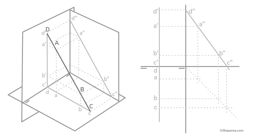
It appears in the dihedral projection as an inclined line parallel to the profile plane. In the downcast plane, it is projected as a line perpendicular to the ground line in both projections, vertical and horizontal (Figure 10).
Line Parallel to the Ground Line
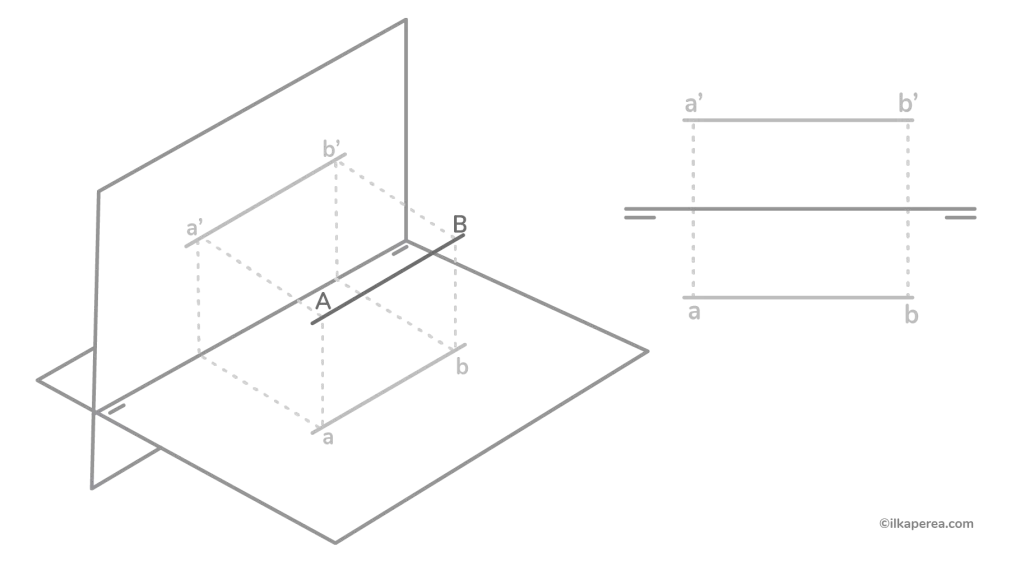
Line parallel to both projection planes (horizontal-frontal). In the tilted projection, it is projected as a line parallel to the ground line in both projections, vertical and horizontal (Figure 11).
Relative Positions of Lines
There are relative positions between lines or between lines and planes:
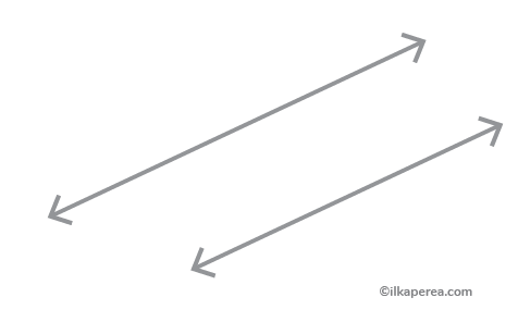
Parallelism
As in plane geometry, two lines are parallel to each other when they never intersect each other; that is to say, they have no point in common in their prolongations (Figure 12). But mainly it is that the distance between both is a constant and since a third line that intersects both has the same angle of inclination as both, it can be deduced that if the angle is different, they are not parallel. Likewise, two parallel lines can determine a plane since they have the virtue of being “coplanar” (i.e., they belong to the same plane).
Intersection
As a matter of fact, the intersection is the point where two geometric objects converge in space. The main characteristic of an intersection is that it contains one or more points in common (Figure 13). The intersection between two lines is called a point of intersection. Likewise, the intersection between two planes is called an intersecting line.
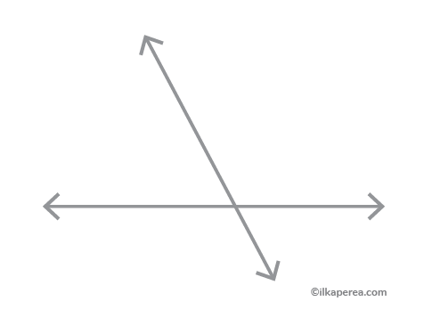
Regardless of the type of intersection, the underlying concept is always the same: the point of intersection must belong to both intersected elements. When the intersection is a line, whether prolonged or not, and it has traces in the projection planes, these traces will always coincide with the traces of the planes to which the line belongs.
Perpendicularity
Perpendicularity in three-dimensional geometry is a little more complex than in plane geometry in terms of its determination. We know that two lines are perpendicular to each other when they form a right angle (90°), but the problem is how to prove this relationship. It can only be determined, or measured, in other words, when one of the two lines is parallel to a projective plane.
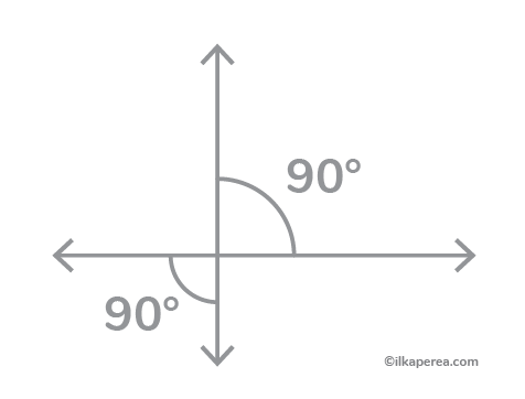
To begin with, perpendicularity can be defined as a special case of intersecting. In fact, it is a particular case of an intersection where the two lines intersect at a right angle. While it is not essential to determine the point of intersection between the two lines, it can make it easier to do so.
In another case, a line is perpendicular to a plane when it is perpendicular to two lines belonging to the plane. This is because perpendicularity to a plane must be determined in two directions. If the line is only perpendicular to one line of the plane, it may not be perpendicular to the plane itself.
Plane
Planes are flat, two-dimensional surfaces that extend infinitely in all directions. They are defined by at least three non-collinear points or a point and two intersecting lines. Planes are used to represent surfaces, like the faces of three-dimensional objects. In descriptive geometry for designers, planes are vital for creating accurate projections and views of complex 3D objects in a 2D format.
The plane is a geometric figure that can be generated by the displacement of a line in space. It consists of two dimensions:
- width
- length
but has:
- no depth.
Shape is the most important characteristic of a plane, and it is determined by the contour of the line that forms the plane’s edges. In graphic construction, a plane is used to define the limits or boundaries of a volume.
Positions of the Planes
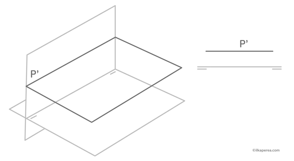
Frontal Plane
It is a plane parallel to the vertical plane of projection; therefore, all its points have the same flight. Its horizontal trace, on which the entire plane is projected horizontally, is parallel to the ground line (Figure 15). The plane is projected vertically in true size.
Horizontal Plane
For its part, the horizontal plane is parallel to the horizontal plane of projection; therefore, all its points have the same elevation (Figure 16). Its vertical trace, on which the entire plane is projected vertically, is parallel to the ground line. The plane is projected horizontally in true size.
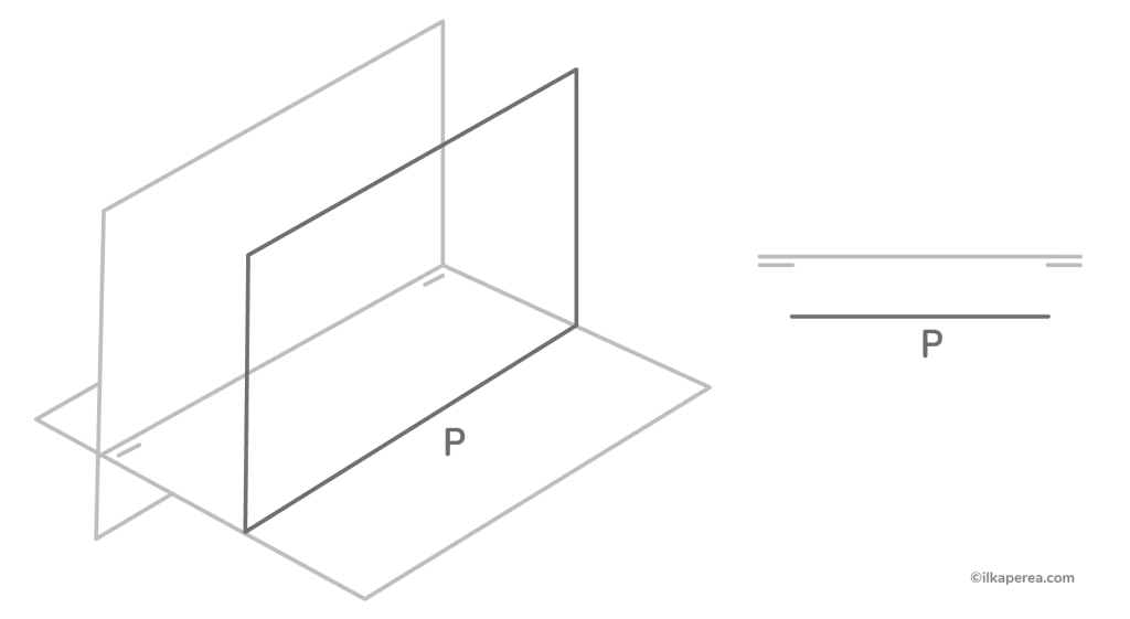
Vertical Plane
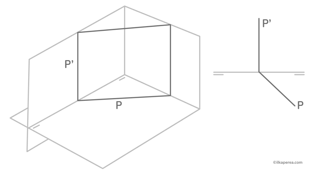
Vertical plane is perpendicular to the horizontal plane of projection; therefore, its vertical trace is perpendicular to the ground line, and the entire plane is projected horizontally on its horizontal trace (Figure 17).
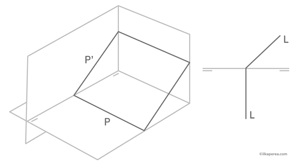
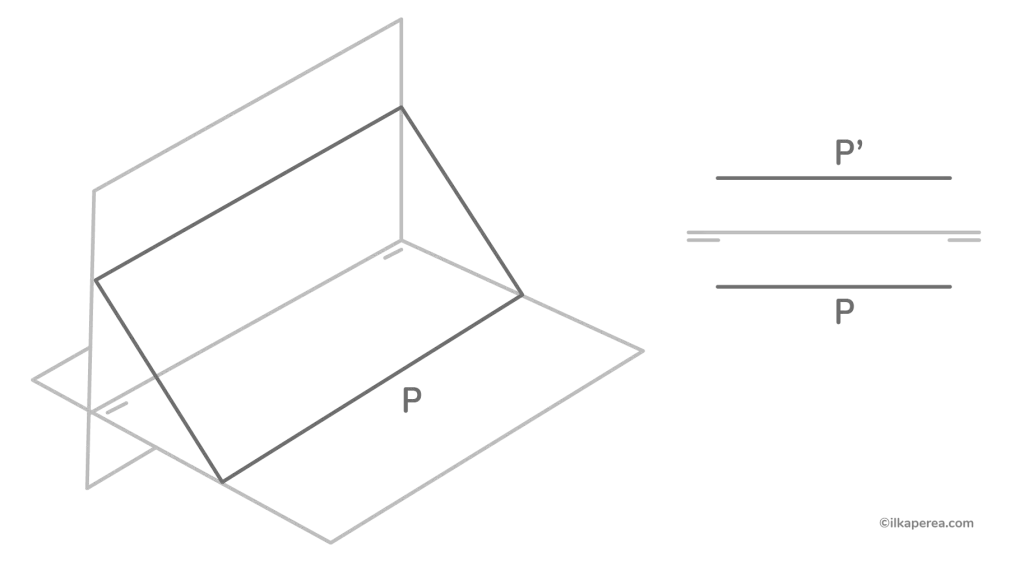
Edge or Vanishing Plane
Edge or Vanishing Plane is perpendicular to the vertical plane of projection; therefore, its horizontal trace is perpendicular to the ground line, and the entire plane is projected vertically on its vertical trace (Figure 18).
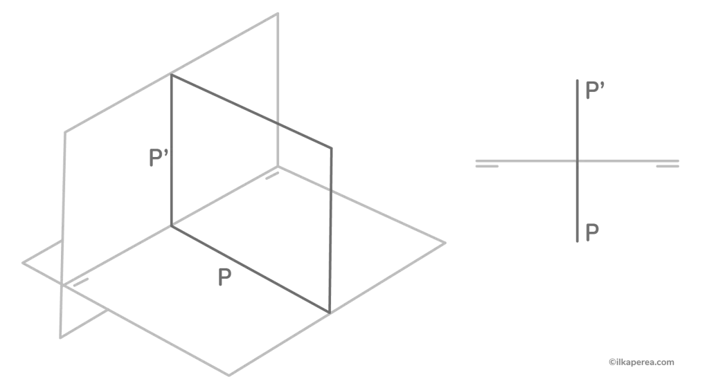
Profile Plane
Profile Plane is perpendicular to the ground line; therefore, it is parallel to the lateral plane, and consequently, all its points have an equal distance to this plane (Figure 19). Its horizontal and vertical traces are perpendicular to the ground line, and the entire plane is projected horizontally and vertically on them. The plane is projected laterally in true size, so it is common in these planes to determine its lateral projection.
Plane Parallel to the Ground Line
Its traces are parallel to the ground line (Figure 20).
Other Concepts in Descriptive Geometry
Graphical Projection Concepts
Graphic projection involves some of the following key principles:
An object refers to any three-dimensional entity, whether physical or abstract, that is being represented and analyzed through graphical techniques to convey its spatial characteristics and dimensions.
A view is a two-dimensional picture of geometric objects. Not just any picture, but a ‘projection’ of geometrical objects onto a planar surface. Imagine a cube drawn on a piece of paper, or a movie “projected” on a screen. Another example that fits very well is the shadow on a flat surface of a three-dimensional object. The shadow view gives an idea of the object but does not show all its dimensions.
An observer refers to a hypothetical point or location from which an object or scene is viewed in order to create a two-dimensional representation on paper.
A projection plane is a flat surface onto which a three-dimensional object is projected. In descriptive geometry for designers, we typically use multiple projection planes, such as the frontal plane, horizontal plane, and profile plane, to represent different views of the object.
Projectors are imaginary lines that connect points on the object to corresponding points on the projection plane. Projectors are perpendicular to the projection plane and determine how the object is transferred onto the 2D surface.
Transferring distance refers to projecting or transferring the image of an object from one view or perspective onto another view or perspective.
Summary
- A point is the most basic element. It does not have width, length, or depth.
- A line is defined by a set of points that extend infinitely in both directions. It has length but does not have width or depth.
- Two lines are parallel to each other when they have no point in common in their prolongations.
- The intersection is the point where two geometric objects converge in space.
- Two lines are perpendicular to each other when they form a right angle.
- A plane is a flat, two-dimensional surface that extends infinitely in all directions. It has length and width but does not have depth.
Some Insights
Descriptive geometry is a field of study that focuses on the geometric representation of objects in two and three dimensions through projections. Among my favorites are isometric projections and conic perspective projections.
In turn, these geometric representations are based on points, lines, and planes. A point is a dimensionless location in space. A line is a one-dimensional geometric object that extends infinitely in two directions. A plane is a two-dimensional geometric object that extends infinitely in all directions.
In essence, these three concepts, interwoven and interconnected, lay the groundwork for the visualization, analysis, and understanding of complex geometric structures and spatial relationships. Moreover, descriptive geometry can be used to understand the spatial relationships between objects, such as their distance and orientation relative to each other.
Any Thoughts?
In the comments section, tell me if you already knew about these descriptive geometry concepts.
Share
Spread the love… and this post!
If you liked it, share this post on your social networks. Smart designers share good things with others.

Bibliography
- Bertoline, G. R., Weibe, E. N., & Hartman, N. W. (2008). Technical Graphics Communication. McGraw-Hill Education.
- Greig, J. (2012). Tutor in a Book’s Geometry. Tutor in a Book.
- Salazar, A. Girón, T. y Salazar, E. (2018). Geometría descriptiva. Santiago de los Caballeros, Universidad Abierta para Adultos (UAPA).
- Schreck, K. R. (2016). Monge’s Legacy of Descriptive and Differential Geometry. Docent Press.
- Woolf, S. (2007). An Elementary Course in Descriptive Geometry. Merchant Books.
- Valencia García, G. (2009). Geometría descriptiva: paso a paso. ed. Bogotá: Ecoe Ediciones.
1 Comment
Join the discussion and tell us your opinion.
[…] Besides, graphic projection involves some of the following key concepts: […]